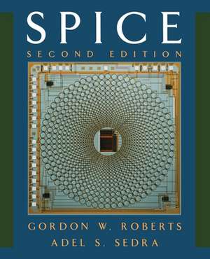
SPICE: The Oxford Series in Electrical and Computer Engineering
Autor Gordon W. Roberts, Adel S. Sedraen Limba Engleză Paperback – 21 noi 1996
Din seria The Oxford Series in Electrical and Computer Engineering
- 23%
 Preț: 1683.18 lei
 - 24%
 Preț: 907.51 lei
 - 22%
 Preț: 955.28 lei
 - 24%
 Preț: 1592.65 lei
 - 27%
 Preț: 1592.17 lei
 - 27%
 Preț: 1594.84 lei
 - 23%
 Preț: 1765.68 lei
 - 24%
 Preț: 1711.28 lei
 - 23%
 Preț: 1764.42 lei
 - 27%
 Preț: 1635.92 lei
 - 27%
 Preț: 1461.67 lei
 - 25%
 Preț: 1661.09 lei
 - 10%
 Preț: 339.22 lei
 - 27%
 Preț: 1468.82 lei
 - 14%
 Preț: 1221.42 lei
Preț: 730.85 lei
Preț vechi: 1001.15 lei
-27%
Puncte Express: 1096
Carte tipărită la comandă
Livrare economică 07-21 decembrie
Livrare prin curier în România Termenul estimat este afișat lângă disponibilitate.
Transport gratuit pentru acest produs Plată online sau ramburs, în funcție de opțiunile comenzii.
Retur gratuit în 14 zile Comandă securizată și suport în română.
Specificații
ISBN-13: 9780195108422
ISBN-10: 0195108426
Pagini: 464
Ilustrații: numerous line figures, tables
Dimensiuni: 188 x 232 x 21 mm
Greutate: 0.79 kg
Ediția:Second.
Editura: Oxford University Press
Colecția OUP USA
Seria The Oxford Series in Electrical and Computer Engineering
Locul publicării:New York, United States
ISBN-10: 0195108426
Pagini: 464
Ilustrații: numerous line figures, tables
Dimensiuni: 188 x 232 x 21 mm
Greutate: 0.79 kg
Ediția:Second.
Editura: Oxford University Press
Colecția OUP USA
Seria The Oxford Series in Electrical and Computer Engineering
Locul publicării:New York, United States
V-ar putea interesa
-
 Reliability Prediction from Burn-In Data Fit to Reliability ModelsJoseph Bernstein-30%Preț: 314.62 lei451.85 lei
 -
 Microelectronic CircuitsAdel S. Sedra-22%Preț: 955.28 lei1222.08 lei
 -
 Guidebook for Managing Silicon Chip ReliabilityMichael PechtPreț: 410.99 lei
 -
 Practical Laser SafetyWinburn-15%Preț: 558.77 lei657.38 lei
 -
 S-Parameters for Signal IntegrityPeter J Pupalaikis-14%Preț: 975.63 lei1134.46 lei
 -
 High-Frequency Magnetic ComponentsMarian K Kazimierczuk-9%Preț: 1010.49 lei1110.42 lei
 -
 -15%Preț: 625.83 lei736.27 lei
 -
 Design and Analysis of Integrator-Based Log-Domain Filter CircuitsGordon W. Roberts-18%Preț: 907.10 lei1106.23 lei
 -
 -15%Preț: 715.71 lei842.00 lei
 -
 Self-Organization in Embedded Real-Time SystemsM. Teresa Higuera-Toledano-15%Preț: 615.41 lei724.01 lei
 -
 Advanced Symbolic Analysis for VLSI SystemsGuoyong Shi-18%Preț: 986.12 lei1202.60 lei
 -
 Sensors and MicrosystemsCorrado Di Natale-18%Preț: 1277.64 lei1558.11 lei
 -
 A Kitchen Course in Electricity and MagnetismDavid NightingalePreț: 258.51 lei
 -
 Debug Automation from Pre-Silicon to Post-SiliconMehdi DehbashiPreț: 401.98 lei
 -
 Trusted Computing for Embedded SystemsBernard Candaele-15%Preț: 671.37 lei789.85 lei
 -
 Model-Driven Design Using IEC 61499Li Hsien Yoong-15%Preț: 665.01 lei782.36 lei
 -
 -15%Preț: 669.81 lei788.01 lei
Cuprins
- Preface
- 1: Introduction to Spice
- 1.1: Computer Simulation of Electronic Circuits
- 1.2: An Outline of Spice
- 1.2.1: Types of Analysis Performed by Spice
- 1.2.2: Input to Spice
- 1.2.3: Output from Spice
- 1.4: Examples
- 1.4.1: Example 1: DC Node Voltages of a Linear Network
- 1.4.2: Example 2: Tranient Response of a 3-Stage Linear Amplifier
- 1.4.3: Example 3: Setting Circuit Initial Conditions During a Tranient Analysis
- 1.4.4: Example 4: Frequency Response of a Linear Amplifier
- 1.5: Spice Tips
- 1.6: Bibliography
- 1.7: Problems
- 2: Operational Amplifiers
- 2.1: Modeling an Ideal Op Amp with Spice
- 2.2: Analyzing the Behavior of Ideal Op Amp Circuits
- 2.2.1: Inverting Amplifier
- 2.2.2: The Miller Integrator
- 2.2.3: A Damped Miller Integrator
- 2.2.4: The Unity-Gain Buffer
- 2.2.5: Instrumentation Amplifier
- 2.3: Nonideal Op Amp Performance
- 2.3.1: Small-Signal Frequency Response of Op Amp Circuits
- 2.3.2: Modeling the Large-Signal Behavior of Op Amps
- 2.4: The Effects of Op Amp Large-Signal Nonidealities on Closed-Loop Behavior
- 2.4.1: DC Transfer Characteristic of an Inverting Amplifier
- 2.4.2: Slew-Rate Limiting
- 2.4.3: Other Op Amp Nonidealities
- 2.5: Spice Tips
- 2.6: Bibliography
- 2.7: Problems
- 3: Diodes
- 3.1: Describing Diodes to Spice
- 3.1.1: Diode Element Description
- 3.1.2: Diode Model Description
- 3.2: Spice as a Curve Tracer
- 3.2.1: Temperature Effects
- 3.3: Zener Diode Modeling
- 3.4: A Half-Wave Rectifier Circuit
- 3.5: Limiting and Clamping Circuits
- 3.6: Spice Tips
- 3.7: Problems
- 4: Bipolar Junction Transistors (BJTs)
- 4.1: Describing BJTs to Spice
- 4.1.1: BJT Element Description
- 4.1.2: BJT Model Description
- 4.1.3: Verifying NPN Transistor Circuit Operation
- 4.2: Using Spice as a Curve Tracer
- 4.3: Spice Analysis as a Curve Tracer
- 4.3.1: Transistor Modes of Operation
- 4.3.2: Computing DC Bias of a PNP Transistor Circuit
- 4.4: BJT Transistor Amplifiers
- 4.4.1: BJT Small-Signal Model
- 4.4.2: Single-Stage Voltage-Amplifier Circuits
- 4.5: DC Bias Sensitivity Analysis
- 4.6: The Common-Emitter Amplifier
- 4.7: Spice Tips
- 4.8: Bibliography
- 4.9: Problems
- 5: Field-Effect Transistors (FETs)
- 5.1: Describing MOSFETs to Spice
- 5.1.1: MOSFET Element Description
- 5.1.2: MOSFET Model Description
- 5.1.3: An Enhancement-Mode N-Channel MOSFET Circuit
- 5.1.4: Observing the MOSFET Current - Voltage Characteristics
- 5.2: Spice Analysis of MOSFET Circuits at DC
- 5.2.1: An Enhancement-Mode P-Channel MOSFET Circuit
- 5.2.2: A Depletion-Mode P-Channel MOSFET Circuit
- 5.2.3: A Depletion-Mode N-Channel MOSFET Circuit
- 5.3: Descrbing JFETs to Spice
- 5.3.1: JFET Element Description
- 5.3.2: JFET Model Description
- 5.3.3: An N-Channel JFET Example
- 5.3.4: A P-Channel JFET Example
- 5.4: FET Amplifier Circuis
- 5.4.1: Effect of Bias Pointn on Amplifier Conditions
- 5.4.2: Small-Signal Model of the FET
- 5.4.3: A Basic FET Amplifier Circuit
- 5.5: Investigating Bias Stability with Spice
- 5.6: Integrated-Circuit MOS Amplifiers
- 5.6.1: Enhancement-Load Amplifiers Including the Body Effect
- 5.6.2: CMOS Amplifier
- 5.7: MOSFET Switches
- 5.8: Describing MESFETs to Spice
- 5.8.1: MESFET Element Description
- 5.8.2: MESFET Model Description
- 5.8.3: Small-Signal MESFET Model
- 5.8.4: A MESFET Biasing Example
- 5.9: Spice Tips
- 5.10: Bibliography
- 5.11: Problems
- 6: Differential and Multistage Amplifiers
- 6.1: Input Excitation for the Differential Pair
- 6.2: Small-Signal Analysis of the Differential Amplifier: Symmetric Conditions
- 6.3: Small-Signal Analysis of the Differential Amplifier: Assymmetric Conditions
- 6.4: Current-Souce Biasing in Integrated Circuits
- 6.5: A BJT Multistage Amplifier Circuit
- 6.6: Spice Tips
- 6.7: Bibliography
- 6.8: Problems
- 7: Frequency Problems
- 7.1: Investigating Transfer Function Behavior Using PSpice
- 7.2: Modeling Dynamic Effects in Semiconductor Devices
- 7.3: The Low-Frequency Response of the Common-Source Amplifier
- 7.4: High-Frequency Response Comparison of the Common-Emitter and Cascode Amplfiers
- 7.5: High-Frequency Response of the CC-CE Amplfier
- 7.6: Spice Tips
- 7.7: Problems
- 8: Feedback
- 8.1: The General Feedback Structure
- 8.2: Determining Loop Gain with Spice
- 8.3: Stability Analysis Using Spice
- 8.4: Investigating the Range of Amplifier Stability
- 8.5: The Effect of Phase Margin on Transient Response
- 8.6: Frequency Compensation
- 8.7: Spice Tips
- 8.8: Bibliography
- 8.9: Problems
- 9: Output Stages and Power Amplifiers
- 9.1: Emitter-Follower Output Stage
- 9.2: Class B Output Stage
- 9.3: Spice Tips
- 9.4: Problems
- 10: Analog Integrated Circuits
- 10.1: A Detailed Analysis of the 741 Op Amp Circuit
- 10.2: A CMOS Op Amp
- 10.3: Spice Tips
- 10.4: Bibliography
- 10.5: Problems
- 11: Filters and Tuned Amplifiers
- 11.1: The Butterworth and Chebyshev Transfer Functions
- 11.2: Second-Order Active Filters Based on Inductor Replacement
- 11.3: Second-Order Active Filters Based on the Two-Integrator-Loop Technology
- 11.4: Tuned Amplifiers
- 11.5: Spice Tips
- 11.6: Bibiliography
- 11.7: Problems
- 12: Signal Generators and Waveform - Shaping Circuits
- 12.1: Op Amp-RC Sinusoidal Oscillators
- 12.1.1: The Wien-Bridge Oscillator
- 12.1.2: An Active-Filter-Tuned Oscillator
- 12.2: Multivibrator Circuits
- 12.3: Precision Rectifier Circuits
- 12.4: Spice Tips
- 12.5: Bibiliography
- 12.6: Problems
- 13: MOS Digital Circuits
- 13.1: NMOS Inverter with Enhancement Load
- 13.2: NMOS Inverter with Depletion Load
- 13.3: The CMOS Inverter
- 13.4: A Gallium-Arsenide Inverter Circuit
- 13.5: Spice Tips
- 13.6: Problems
- 14: Bipolar Digital Circuits
- 14.1: Transistor-Transistor Logic (TTL)
- 14.2: Emitter-Coupled Logic (ECL)
- 14.3: BiCMOS Digital Circuits
- 14.4: Bibliography
- 14.5: Problems
- A.1: Diode Model
- A.2: BJT Model
- A.3: JET Model
- A.4: MOSFET Model
- A.5: MESFET Model
- A.6: Bibliography
- Index